(Estimated time: 5 minutes plus time for review questions)
Take-home points:
-
- Echo images are acquired as a series of lines.
- The locations of structures in each line are calculated from the time required for a sound pulse to travel out from the transducer, reflect from a structure, and return.
Ultrasound images are formed by a very different process than the optical images formed by your eyes or a digital camera:

-
- The ultrasound transducer acts as both the source and the receiver of the sound waves, unlike the eye which only receives light.
- The ultrasound image is acquired as a series of lines, while your eye/a camera acquires an image as a grid of pixels.
Ultrasound images are based on echolocation, the same process used by bats and radar to locate structures, shown in Figure 1.
-
-
- A sound wave pulse is sent out from the ultrasound transducer (Figures 1 and 2)
- That sound pulse is reflected from the structure being imaged and returns to the transducer, where it is detected and the time of arrival is recorded.
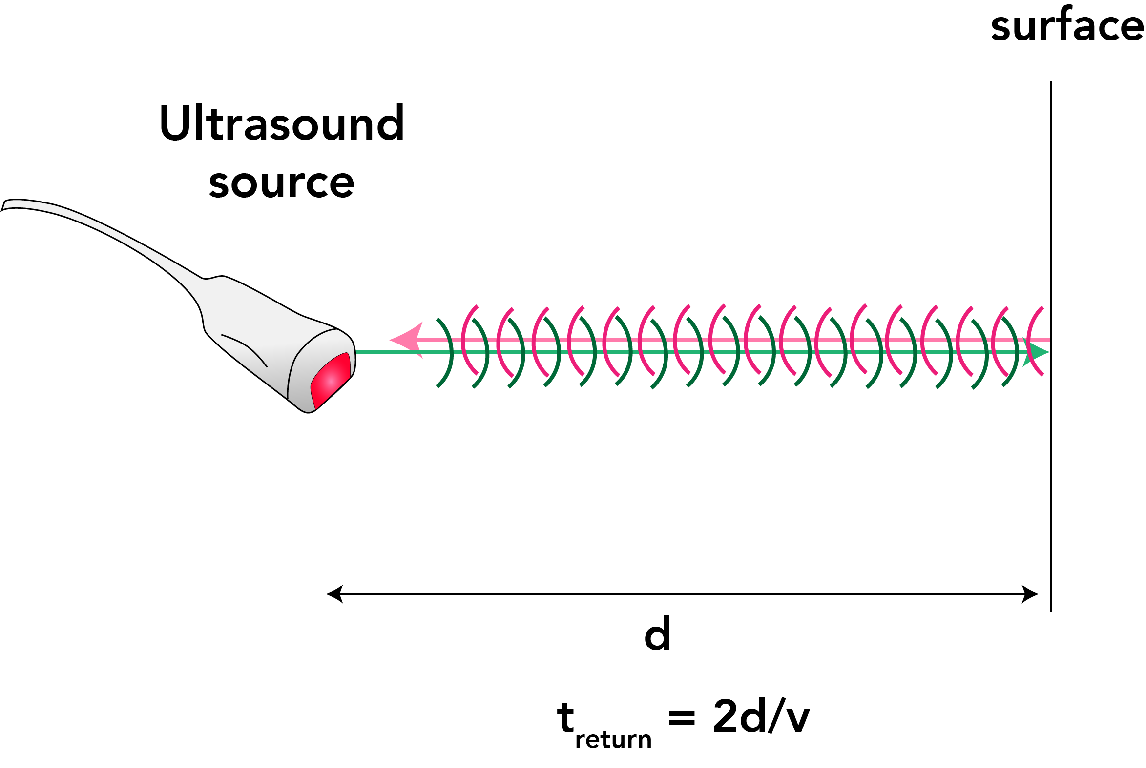
Figure 2: Ultrasound imaging works by recording the time elapsed from when a sound wave is sent out from the transducer until it returns due to reflection. Lines show the direction of travel of the sound wave, while curved surfaces represent the series of wave peaks or “crests” (see lesson 2). Outgoing wave, green; reflected wave, pink. - The distance d to the reflecting object is calculated from the time t elapsed from when the sound pulse is launched until it returns (Figure 2).
- The pulse travels a total distance of 2d at speed v, the speed of the sound pulse in the medium, so d is related to t according to 2d = vt. This can be rearranged into the form t =2d/v.
- If there are multiple reflecting sources along the line of the sound pulse, multiple echoes will be received.
- A single sound wave pulse gives the information needed to construct a single line of the image.
-
A complete ultrasound image is made up of many such lines (Figure 3).
-
-
- The data are acquired by directing sound pulses out of the transducer along adjacent directions filling the sector angle of the image.

Figure 3: Each line of a 2D echo image is reconstructed from the echoes of a wave pulse sent out in that direction. Adapted from Snider, Fig. 1.2. - For each wave pulse, the software of the ultrasound instrument combines the echo return time with information about the direction in which the pulse was sent.
- Doing this for each pulse builds up the image out of its constituent lines. The lines need to be closely spaced enough to distinguish the structures of interest (see Figure 4).
- In Lesson 4 we will discuss different ways this is implemented.
-
In contrast, optical images are formed by a lens focusing light.
-
-
-
- The focused light forms a planar pattern that matches the original object and is detected on the retina of the eye or the sensor of the camera.
- Each pixel of the sensor detects the light coming from a corresponding region on the original object.

Figure 4. Scan lines overlaid on schematic of heart; for structures to be successfully imaged, lines need to be sufficiently closely spaced. Fig 26-4 from Echocardiography. - The entire image is acquired simultaneously.
-
-
Review questions
-
-
- Is the entire ultrasound image acquired simultaneously, or are different parts of the image acquired in a rapid sequence? (Answer)
- An ultrasound image shows two objects, one 2 cm from the transducer and one 4 cm from the transducer. The speed of sound in tissue is 1,580 m/s = 1.58 m/ms = 158 cm/ms. To make the numbers easy, let’s round off to 200 cm/ms. How long does it take the echo from the first structure to arrive? From the second? (Answer)
-