(Estimated time: 15 minutes plus review questions)
Take-home messages:
- Lower frequency ultrasound penetrates more deeply but produces images with poorer resolution.
- To image structures effectively, the ultrasound pulse needs to strike the structure close to perpendicularly; pulses that strike close to parallel to the structure’s surface do not reflect back to the transducer.
- Ultrasound artifacts can result from structures that refract (change the direction of) the beam.
Ultrasound traveling through tissue is attenuated in a frequency-dependent manner, making the choice of frequency clinically important.
-
- As a wave travels into tissue, energy is gradually absorbed by the tissue, limiting the depth of structures that can be imaged.
- The wave loses energy as it goes deeper, reducing the wave’s amplitude and power (rate of energy delivery from wave). Intensity (power per area) is thus also reduced.
- This energy loss is called attenuation.
- That energy goes into altering the energy of individual molecular bonds in the medium, and gradually heating the absorbing tissue.
Lower frequencies, corresponding to longer wavelengths, penetrate more deeply. However, longer wavelengths produce lower-resolution images (Lesson 2). Consequently, the choice of frequency for imaging is a tradeoff between imaging depth and resolution.
Interfaces between different tissue types cause reflection and change of direction of ultrasound pulses
Whenever a wave encounters an interface between two media in which the wave speed and/or density are different (e.g. blood versus endocardium), the wave energy is divided between reflection and transmission. Transmitted waves typically change direction, which is the source of many imaging artifacts.
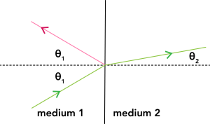
If the interface is flat and perfectly smooth, the reflected and transmitted wave directions follow the geometric rules shown in Figure 1.
-
- The angle of reflection equals the angle of incidence (labeled θ1 in the figure). 1 Consequently, the reflected wave (pink) only comes directly back to the transducer if the probe wave (green) strikes the surface perpendicularly. If the probe wave strikes close enough to perpendicular, the reflected wave returns close enough to the probe wave to still strike the transducer.
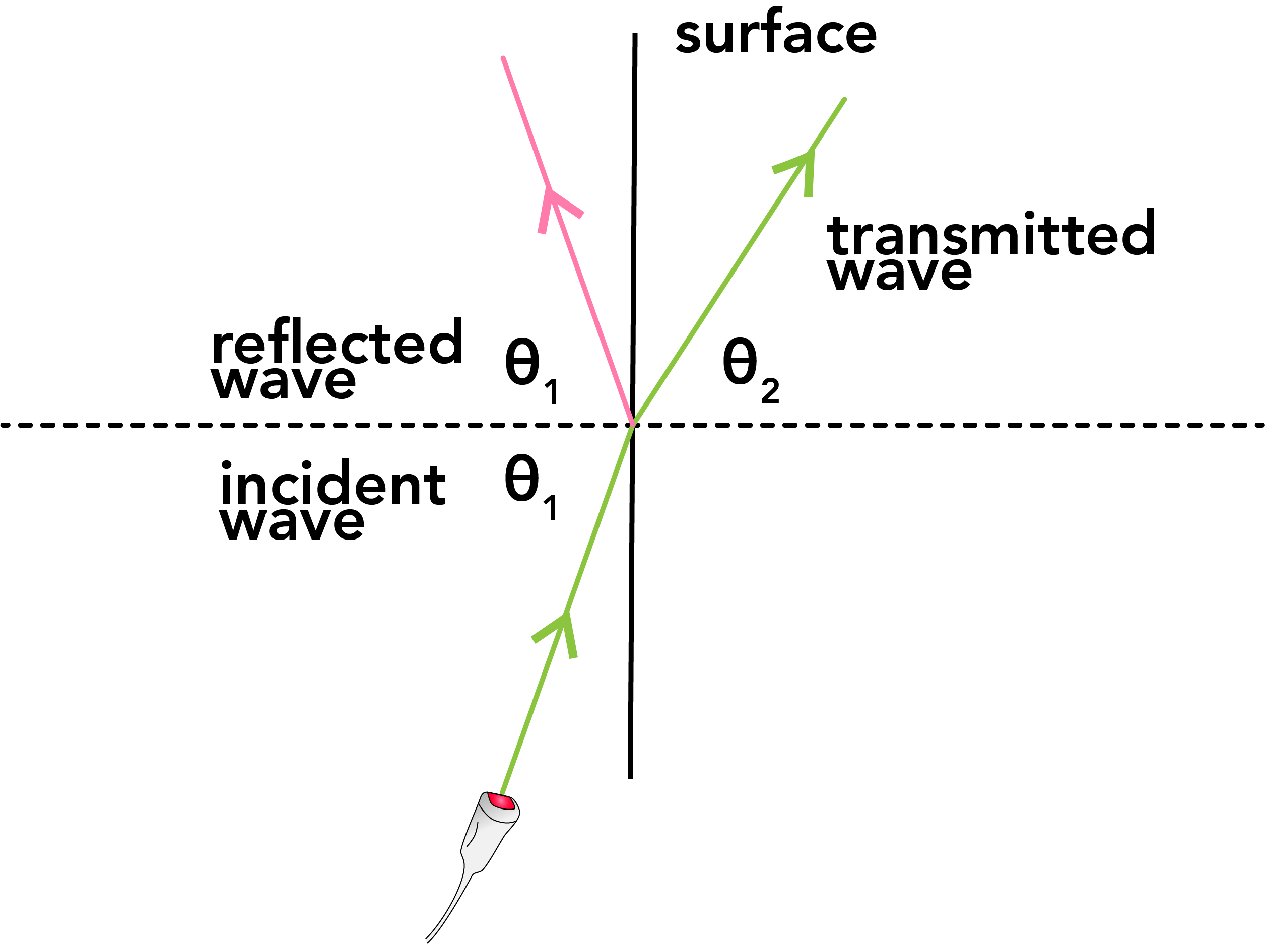
Figure 2. An ultrasound wave striking a surface nearly parallel does not return to the transducer. - If the ultrasound wave strikes the interface close to parallel (Fig. 2), the reflected wave will continue to travel away from the transducer. Consequently, surfaces close to parallel to the ultrasound wave are nearly invisible.
- The angle of transmission, also called the angle of refraction (labeled θ2 in Fig. 2), is usually different from the angle of incidence, so the transmitted wave is also typically redirected. It is determined by the incidence angle and the wave speeds in the two materials according to a relationship sometimes called Snell’s Law:

- If the wave speeds are very similar, the angles of incidence and refraction are also very similar and the transmitted wave does not change direction much.

Figure 3: Mechanism of a double-image artifact in 2D echocardiography. An ultrasound pulse reflected from point 1 of the LV endocardium returns to the transducer and is shown appropriately as a bright spot in the correct position in the image. Later in the scan, an ultrasound pulse is refracted by intervening tissue, so that the beam is reflected back to the transducer from point 2. However, this reflected signal is interpreted as coming from along the transmission scan line (point 3) leading to an image artifact. Ao = aorta in cross section. From Otto, Fig. 1.16. Note: this figure shows an unrealistically large refraction for clarity of the schematic.
- The angle of reflection equals the angle of incidence (labeled θ1 in the figure). 1 Consequently, the reflected wave (pink) only comes directly back to the transducer if the probe wave (green) strikes the surface perpendicularly. If the probe wave strikes close enough to perpendicular, the reflected wave returns close enough to the probe wave to still strike the transducer.
Image artifacts can arise when waves are refracted through one structure and then reflect from the structure of interest. As the intermediate refraction cannot be accounted for, the structure is displayed in the wrong location, as shown in Figure 3.
Reflected wave characteristics
-
- The reflected wave has the same frequency and wave speed as the original wave, and hence the same wavelength. (It has the same frequency, because it’s generated by the vibrations of the medium at the interface; it has the same wave speed, because it’s in the same medium.)
- The amount of energy reflected depends on both the density and the sound speed of each of the two media. (Density and sound speed are correlated, so you can think of it as just depending on the density.)
- Large differences in tissue density lead to large amounts of reflection, while interfaces between very similar media cause less reflection.
- Greater image detail and contrast are therefore obtained for structures that present greater differences in density to the incident wave.
Transmitted wave characteristics
-
- All the energy that’s not either reflected or absorbed continues to travel forward through the new medium.
- Usually the direction changes (“refraction”) as discussed previously. Changes of direction are typically small but can nonetheless lead to artifacts by the mechanism shown in Fig 3.
- The frequency remains the same; the wave speed and hence wavelength are different due to the different medium.
Avoiding unwanted reflections clinically
-
- Strong reflection is desirable from the structures that are to be imaged, but causes problems if it prevents the ultrasound beam from reaching the structures of interest. For example, prosthetic valves are strong reflectors and can conceal (“shadow”) structures behind them, as shown in Fig. 4.

Figure 4. This apical 4 chamber view of a patient who has had the mitral valve replaced with a prosthetic valve shows “shadowing” of the left atrium from the prosthesis, such that one cannot evaluate the left atrium. LV, left ventricle; LA, left atrium. - At air-tissue interfaces, due to the density difference, nearly all ultrasound is reflected, so very little is transmitted. (Ultrasound is also rapidly attenuated in air.)
- Imaging of cardiac structures generally cannot be done if the ultrasound pulse must pass through the lungs, as it will be nearly all reflected from the air-filled lungs.
- If the transducer is outside the patient, water-based gel is used between the transducer and the patient’s skin to eliminate intervening air.
- Strong reflection is desirable from the structures that are to be imaged, but causes problems if it prevents the ultrasound beam from reaching the structures of interest. For example, prosthetic valves are strong reflectors and can conceal (“shadow”) structures behind them, as shown in Fig. 4.
Review questions
- You want to image two structures, one deeper in the patient than the other. Your initial choice of frequency allows you to see the shallow structure but not the deep structure. Should you increase or decrease the ultrasound frequency? What will happen to the resolution of your image? (Answer)
- If you see a double image of something, what is one possible explanation? How could you change your imaging strategy to eliminate the double image? (Answer)
- Figure 4 shows two different images of a patient’s heart from two different windows and thus two different angles of insonation. From the subcostal sagittal window (left panel), the atrial septum is readily seen with no defect. From the apical 4 chamber view (right panel), the atrial septum is poorly seen and may appear to be deficient. Why? (Answer)

Images for Review Question 3. RA = right atrium; LA = left atrium.
Footnotes
-
-
- Different conventions exist for whether the angle is measured from the dotted perpendicular shown in the figures here, or whether it is measured from the surface itself. The standard convention used here is to measure it from the perpendicular, but you may see other approaches. The most important thing is to understand the geometry so that regardless of where the angle is measured from, it makes sense that a wave that strikes the surface perpendicularly comes directly back. [Back]
-